Damper Durability Test Systems
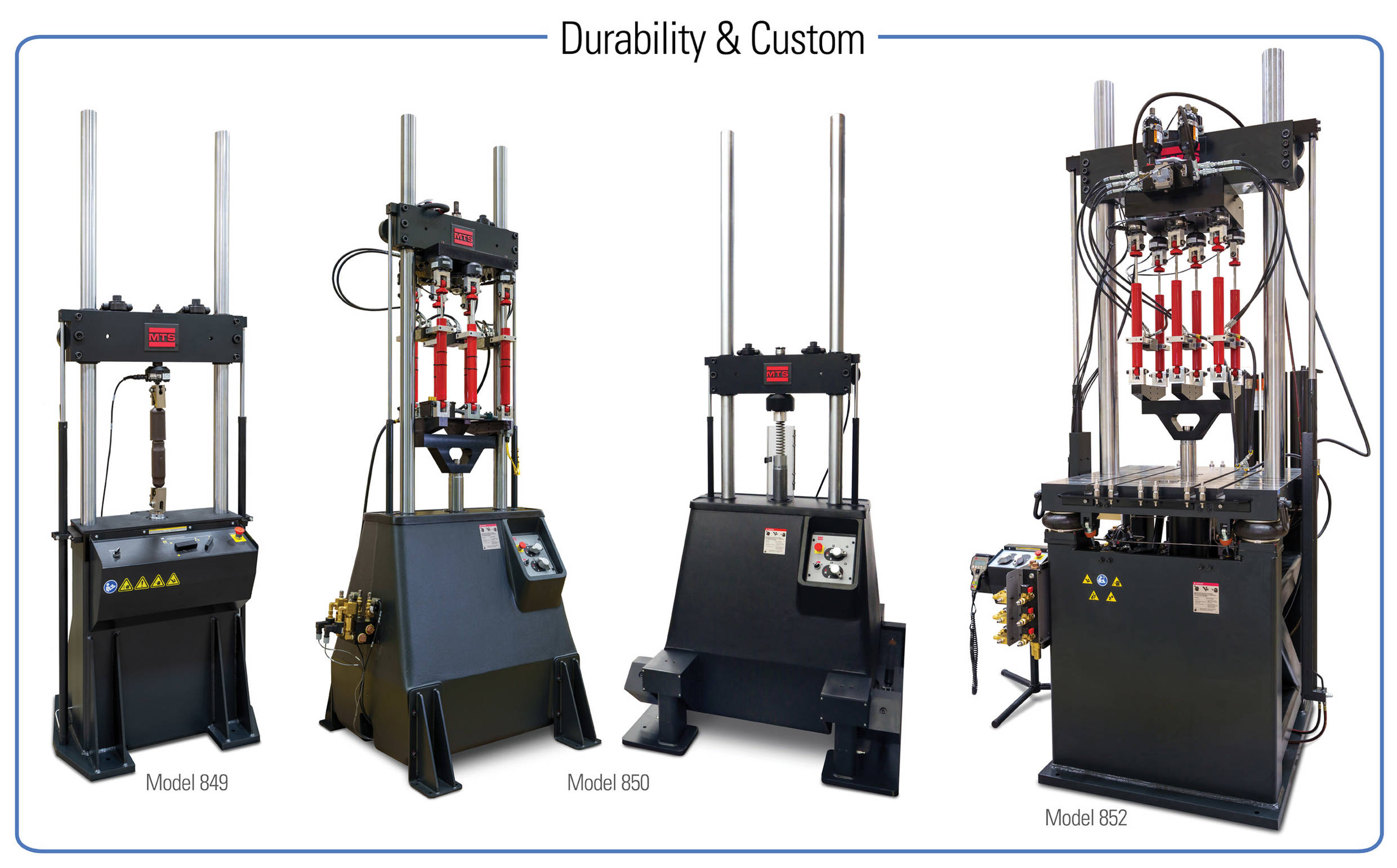
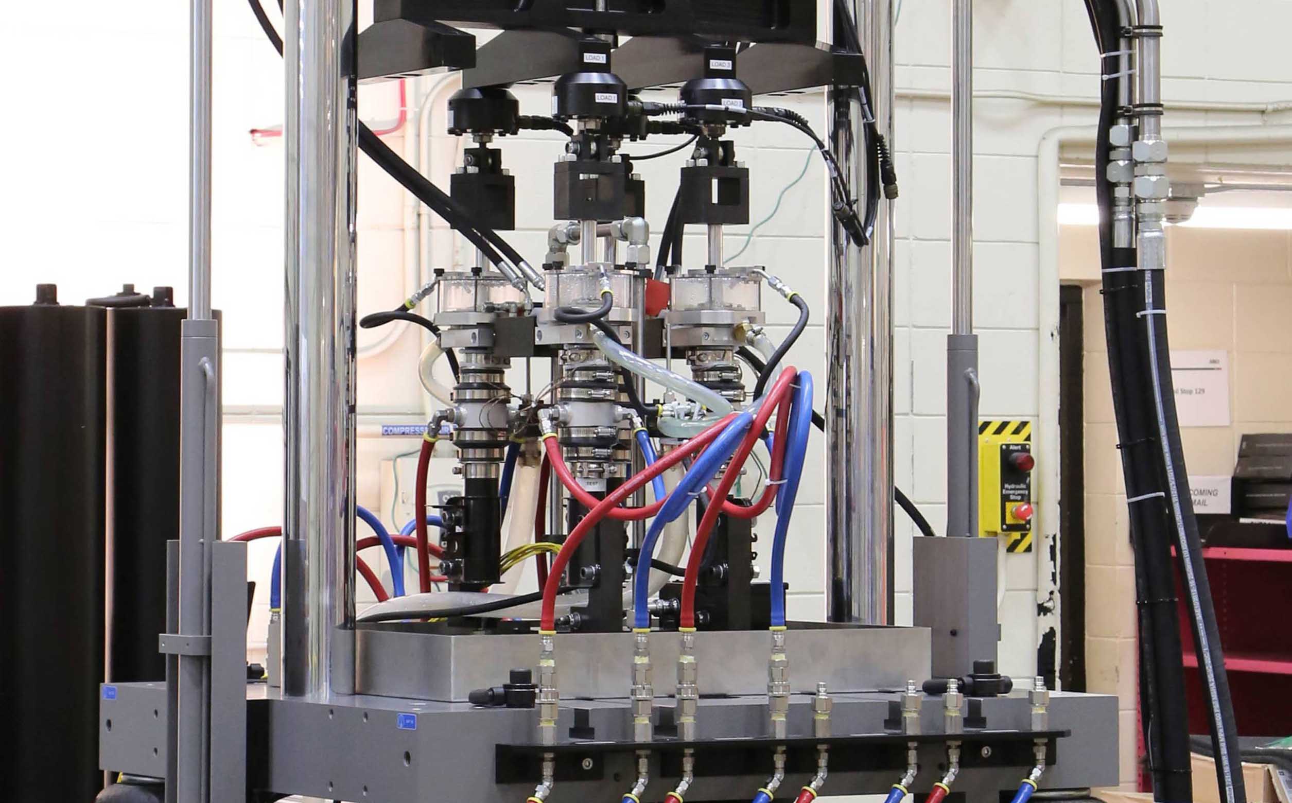
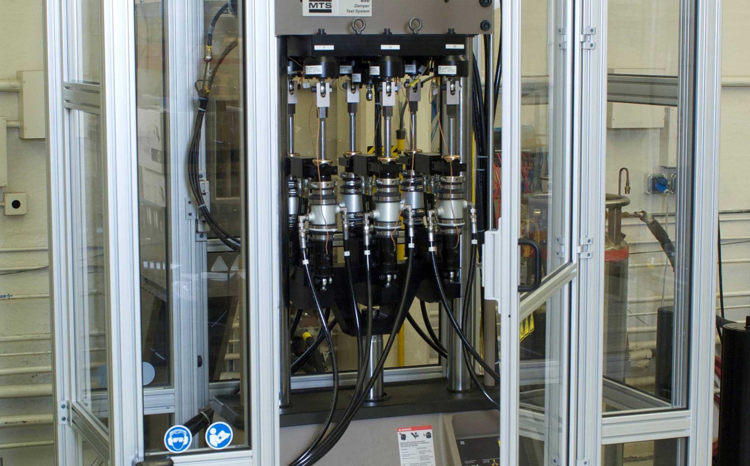
Subject single or multiple damper specimens to millions of durability cycles, or run short bursts of high-performing cycles to measure damping characteristics. MTS damper durability systems combine highly stiff, self-supporting bases to withstand high inertial loading and selectable three-stage servovalves to perform high velocity durability testing on even the largest dampers and struts.
Applications
- Durability
- Characterization
Test Specimens
- Dampers
- Struts
Key Product Features
Versatile
Models 850 & 852 deliver the force required for multi-specimen durability testing while supporting an array of optional hardware for a wide variety of performance testing
Accurate / Repeatable
Capable of generating a full spectrum of control waveforms, including sine, ramp, square, sine-on-sine, sine sweep, dual rate sine, dual rate ramp and user defined block cyclic.
Advanced Safety Features
A certified, safety-rated Programmable Logic Controller (PLC) ensures the safety of human operators and ISO 13849 compliance
Efficient Operation
MTS Damper Testing Software enables easy test setup, flexible yet comprehensive data acquisition, automated test data reports and numerous methods of presentation and analysis
Model Comparison
Model 849
- Durability (single specimen)
- Performance Characterization (Programmable)
- 15.0 – 25.0 kN
- Linear Servohydraulic
- MTS Damper Testing Software
Model 850
- Durability (1-6 specimens)
- Performance Characterization (Programmable)
- 25.0 – 67.0 kN
- Linear Servohydraulic
- MTS Damper Testing Software
Model 852
- Durability (1-8 specimens)
- Performance Characterization (Programmable)
- 25.0-150.0 kN
- Linear Servohydraulic
- MTS Damper Testing Software
- T-Slot table for supporting optional hardware
- Position-able column/cross-head/actuator assembly
Custom Configurations
- Testing in the presence of mud and slurry contaminants
- High-velocity testing
- Magneto-Rheological (MR) damper testing
- Testing of inverted or angled specimens
- Production quality testing
- and more
Technical Overview

|
|
Units |
Model 849.15 |
Model 849.25 |
Model 849.25 HV |
|
Actuator Maximum Dynamic Force |
kN |
15 |
25 |
25 |
|
kip |
3.3 |
5.5 |
5.5 | |
|
Actuator Rod Diameter |
mm |
70 |
||
|
Actuator Stroke |
kN |
250 |
||
|
Actuator Hydrostatic Bearing |
|
Standard |
||
|
Actuator Anti-Rotate |
|
Standard |
||
|
Servovalve |
lpm |
126 |
188 |
250 |
|
gpm |
33 |
50 |
66 | |
|
Friction Force Servovalve |
lpm |
3.8 |
3.8 | 3.8 |
|
gpm |
1 |
1 | 1 | |
|
Servovalve Shutoff |
|
Manual |
||
|
Hydraulic Low Flow |
|
Standard, limits actuator to 10 mm/s |
||
|
Friction Force Load Cell |
kN |
7 |
||
|
lbs |
1500 |
|||
|
Sideload |
|
Hydraulic, dynamic (optional) |
||
|
Pneumatic, static (optional) |
||||
|
Accumulators |
liters |
8 |
15 |
22.7 |
|
Test Space |
mm |
1200 |
||
|
HSM |
|
Integral to accumulator manifold |
||
|
Performance:
|
m/s @ kN |
3.2 @ 0 |
2.9 @ 0 |
3.75 @ 0 |
|
2.3 @ 5 |
2.5 @ 5 |
3.25 @ 5 | ||
|
0.7 @ 10 |
2.0 @ 10 |
2.75 @ 10 | ||
|
|
1.4 @ 15 |
2.25 @ 15 | ||
|
|
0.6 @ 18 |
1.4 @ 20 | ||

|
Machine Specifications |
Units |
Model 850.25 |
Model 850.50 |
|
Actuator Rod Diameter |
mm |
80 |
80 |
|
in |
3.15 |
3.15 |
|
|
Test Space (Actuator Face to Load Cell) |
|||
|
maximum |
mm |
1560 |
1540 |
|
minimum |
mm |
160 |
132 |
|
Frame Dynamic Load Rating |
kN |
50 |
50 |
|
kip |
11 |
11 |
|
|
Floor Mount |
|
Frame Bolted to Concrete (optional vibration isolation system available) |
|
|
HSM |
lpm |
Integral to Accumulator manifold, 300 lpm max |
|
|
Actuator Hydrostatic Bearing |
Yes |
||
|
Actuator Stroke |
mm |
250 |
250 |
|
in |
10 |
10 |
|
|
Heavy Duty Anti-Rotate |
|
Yes |
|
|
Safety Low Flow |
|
Yes |
|
|
Accumulator |
l |
19 Liter Pressure and Return |
|
|
Durability Testing Specifications |
||||||
|
Maximum continuous peak velocity of 100 mm stroke (peak to peak) and 12.5 kN load sine wave command |
|
Maximum continuous peak velocity of 100 mm stroke (peak to peak) and 25 kN load sine wave command |
||||
|
Model 850.25 |
|
Model 850.50 |
||||
|
HPU |
HZ Power |
M/S |
|
HPU |
HZ Power |
M/S |
|
505.20 |
60 |
0.9 |
|
505.20 |
60 |
0.4 |
|
505.20 |
50 |
0.7 |
|
505.20 |
50 |
0.3 |
|
505.30 |
60 |
1.5 |
|
505.30 |
60 |
0.8 |
|
505.30 |
50 |
1.2 |
|
505.30 |
50 |
0.6 |
|
505.60 |
60 |
3.5 |
|
505.60 |
60 |
1.9 |
|
505.60 |
50 |
2.8 |
|
505.60 |
50 |
1.6 |
|
505.90* |
60 |
3.6 |
|
505.90 |
60 |
3 |
|
505.90 |
50 |
3.6 |
|
505.90 |
50 |
2.4 |
|
|
|
|
|
505.180* |
60 |
4 |
|
|
|
|
|
505.180* |
50 |
4 |
|
*HSM on frame limits flow to 300 Lpm (80 gpm). Add MTS Model 293 HSM for HPUs with output greater than 300 Lpm. |
||||||
|
Performance Testing Specifications |
|||
|
Maximum peak velocity for 3 cycles of 100 mm stroke (peak to peak), sine wave command |
|||
|
Model 850.25 |
Model 850.50 |
||
|
4 m/s |
No Load |
5 m/s |
No Load |
|
3.5 m/s |
5000 N Load |
4.5 m/s |
5000 N Load |
|
2.8 m/s |
10000 N Load |
4.0 m/s |
10000 N Load |
|
1.8 m/s |
15000 N Load |
3.0 m/s |
20000 N Load |
|
1.0 m/s |
15000 N Load |
1.2 m/s |
30000 N Load |

|
Machine Specifications |
Units |
Model 852.25 |
Model 852.50 |
Model 852.67 |
|
|
Actuator Rod Diameter |
mm |
80 |
80 |
80 |
|
|
in |
3.15 |
3.15 |
3.15 |
||
|
Test Space (Actuator Face to Load Cell) |
|
||||
|
maximum |
mm |
1575 |
1575 |
1575 |
|
|
minimum |
mm |
180 |
180 |
180 |
|
|
Frame Dynamic Load Rating |
kN |
67 |
67 |
67 |
|
|
kip |
15 |
15 |
15 |
||
|
Floor Mount |
|
Frame Bolted to Concrete (optional vibration isolation system available) |
|||
|
HSM |
lpm |
Integral to Accumulator manifold, 284 lpm max |
|||
|
Actuator Hydrostatic Bearing |
Yes |
||||
|
Actuator Stroke |
mm |
250 |
250 |
250 |
|
|
in |
10 |
10 |
10 |
||
|
Heavy Duty Anti-Rotate |
|
Yes |
|||
|
Safety Low Flow |
|
Yes |
|||
|
Accumulator (pressure and return) |
l |
19 |
19 |
38 |
|
|
Durability Testing Specifications |
||||||||||
|
Maximum sine wave continuous peak velocity for durability testing |
||||||||||
|
Model 852.25 |
|
Model 852.50 |
|
Model 852.67 |
||||||
|
HPU |
HZ Power |
M/S |
|
HPU |
HZ Power |
M/S |
|
HPU |
HZ Power |
M/S |
|
505.20 |
60 |
0.9 |
|
505.20 |
60 |
0.5 |
|
505.20,_60_Hz |
60 |
0.3 (33.5_kN_of_load) |
|
505.20 |
50 |
0.7 |
|
505.20 |
50 |
0.4 |
|
505.20,_50_Hz |
60 |
0.2 (33.5_kN_of_load) |
|
505.30 |
60 |
1.6 |
|
505.30 |
60 |
0.9 |
|
505.30 |
60 |
0.6 (33.5_kN_of_load) |
|
505.30 |
50 |
1.3 |
|
505.30 |
50 |
0.7 |
|
505.30 |
50 |
0.4 (33.5_kN_of_load) |
|
505.60 |
60 |
3.2 |
|
505.60 |
60 |
2 |
|
505.60 |
60 |
1.4 (33.5_kN_of_load) |
|
505.60 |
50 |
2.9 |
|
505.60 |
50 |
1.7 |
|
505.60 |
50 |
1.1 (33.5_kN_of_load) |
|
505.90*# |
60 |
3.2 |
|
505.90* |
60 |
3.2 |
|
505.90* |
60 |
2.2 (33.5_kN_of_load) |
|
505.90*# |
50 |
3.2 |
|
505.90 |
50 |
2.6 |
|
505.90 |
50 |
1.7 (33.5_kN_of_load) |
|
|
|
|
|
505.180*# |
60 |
3.6 |
|
505.180*# |
60 |
2.9 (33.5_kN_of_load) |
|
|
|
|
|
505.180*# |
50 |
3.6 |
|
505.180*# |
50 |
2.9 (33.5_kN_of_load) |
|
* Due to a flow limit of 284 lpm with the standard on/off HSM, an optional 293 HSM is required to meet this performance. |
||||||||||
|
# Maximum velocity limited at this specimen load. |
||||||||||
|
Performance Testing Specifications |
||||||
|
Maximum peak velocity for 3 cycles of 100 mm stroke (peak to peak), sine wave command |
||||||
|
Model 850.25 |
Model 850.50 |
Model 852.67 |
||||
|
4.0 m/s |
No Load |
5.0 m/s |
No Load |
3.8 m/s |
No Load |
|
|
3.6 m/s |
5000 N Load |
4.5 m/s |
5000 N Load |
3.6 m/s |
10 kN Load |
|
|
3.0 m/s |
10000 N Load |
4.0 m/s |
10000 N Load |
3.1 m/s |
20 kN Load |
|
|
2.2 m/s |
15000 N Load |
3.0 m/s |
20000 N Load |
2.5 m/s |
30 kN Load |
|
|
1.5 m/s |
18000 N Load |
1.2 m/s |
30000 N Load |
1.7 m/s |
40 kN Load |
|

-
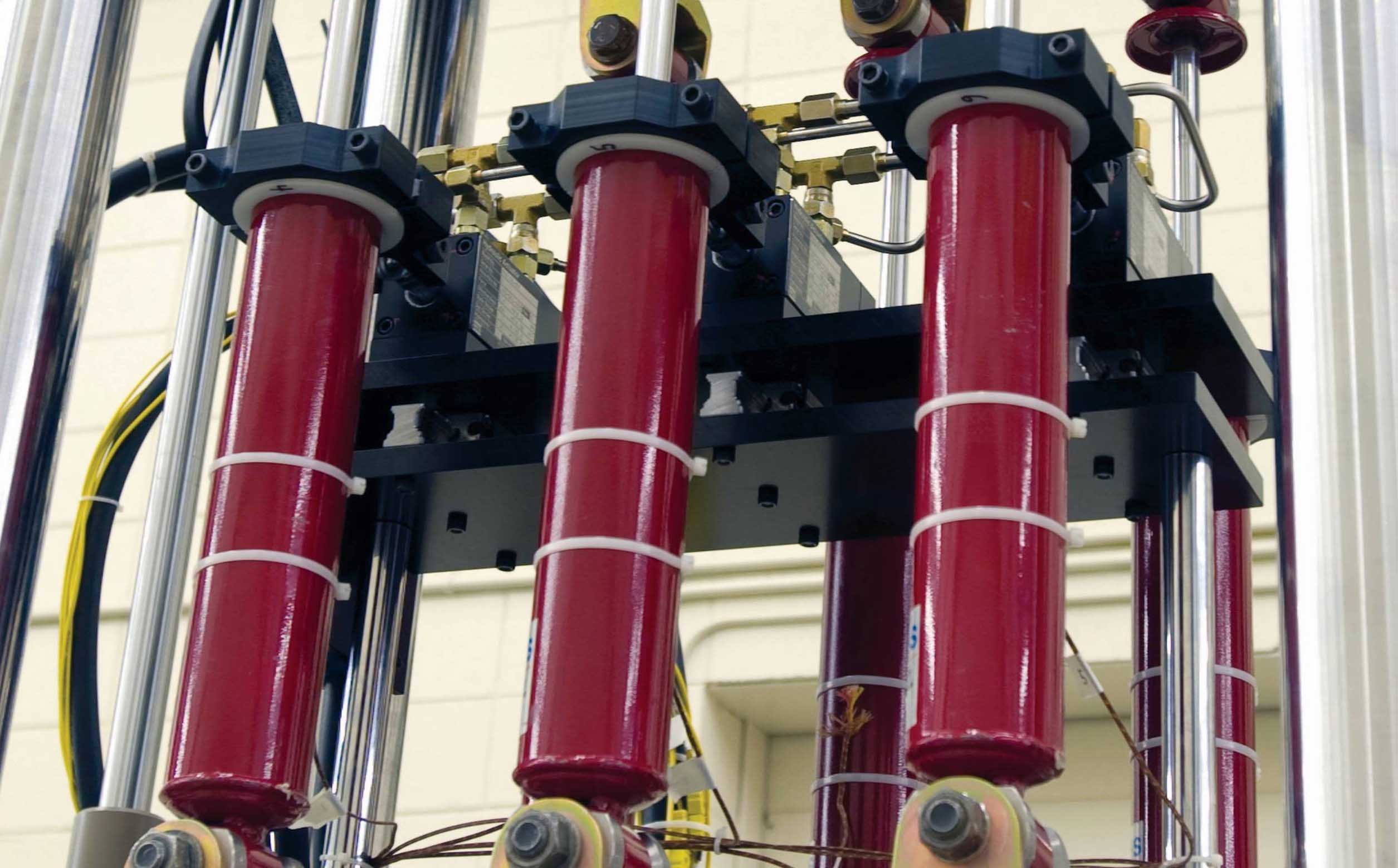
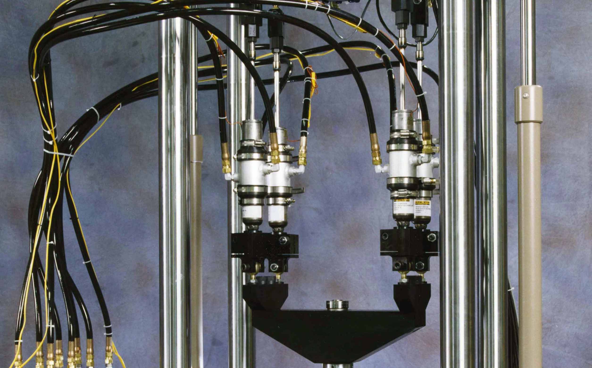
Servovalves (high and low flow modes): Achieve higher-precision in low-velocity tests while in low-flow mode with the addition of secondary servo valves.
-
Custom Accumulation: Increase system performance with additional accumulators. System can be customizable to meet unique testing needs.
-
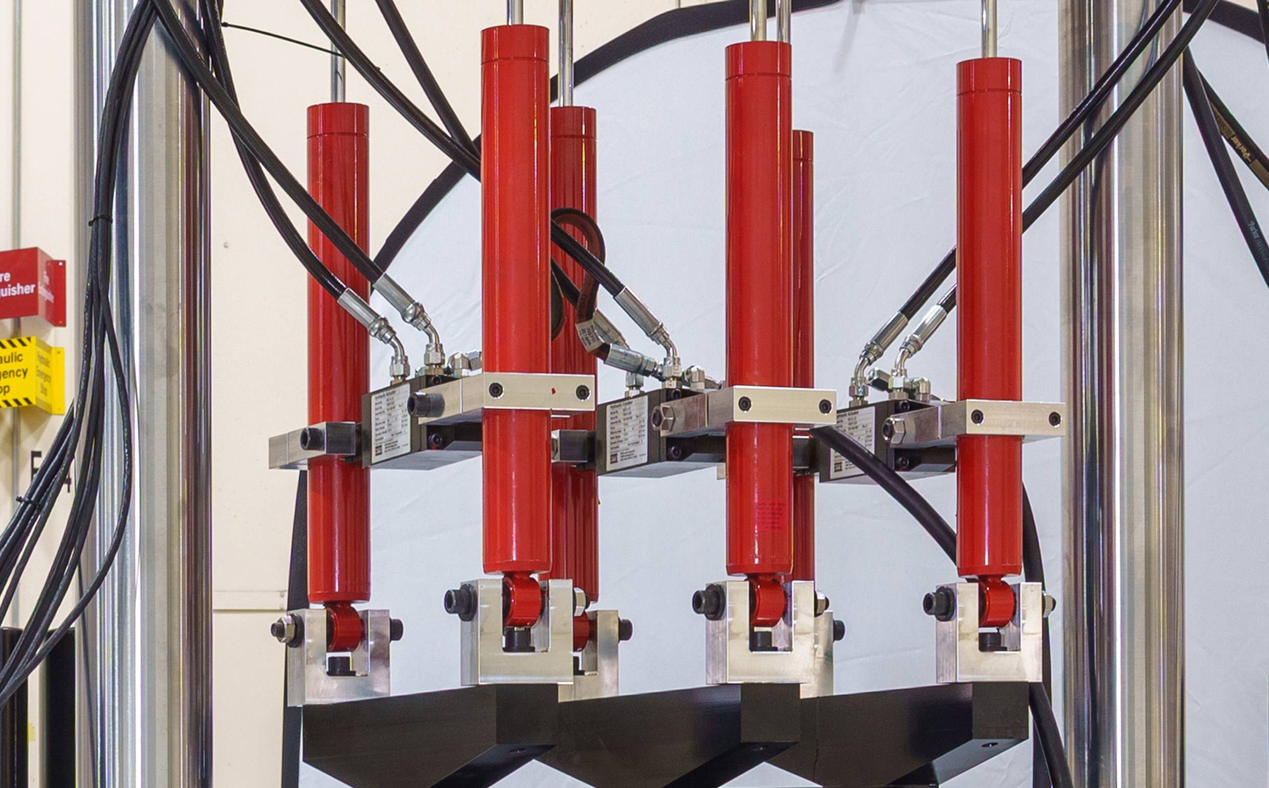
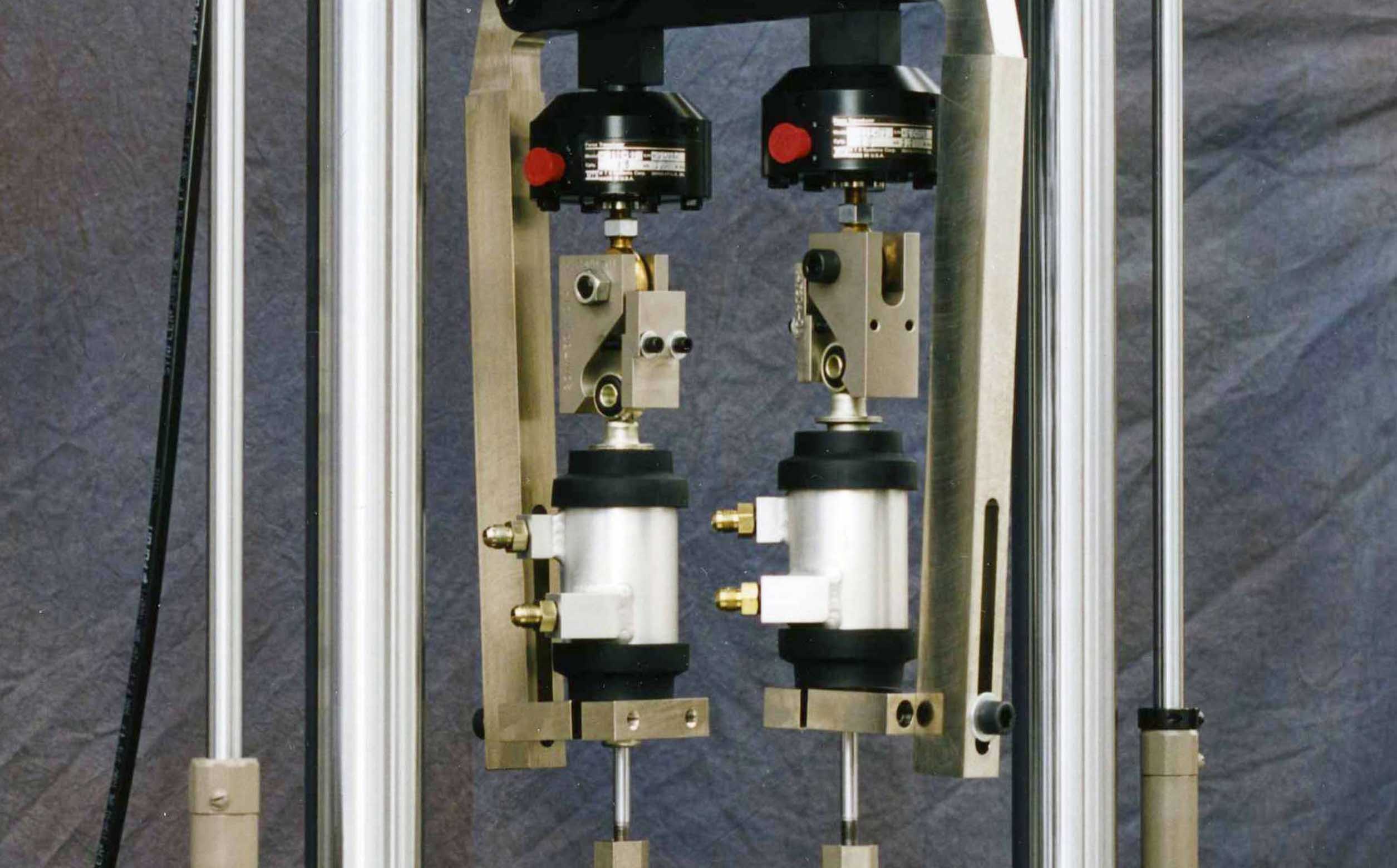
Multi-specimen Fixtures: Enable testing of up to 8 specimens simultaneously. Individual force transducers for each specimen are used to provide accurate data acquisition
-
Side-load Actuators: Simulate real-world loading conditions by providing an adjustable lateral force on damper test specimens.
-
Environmental Chamber: Test dampers in real-world hot and cold conditions with an environmental chamber mounted in the test frame.
-
Water-jacket Cooling: Reduce testing downtime by keeping dampers within a test specification’s required temperatures ranges.
-
Vibration Isolation: Reduce force transmission into the floor and allow test systems to be installed into facilities sensitive to vibration.
-
Safety Enclosures: CE-rated PLc and PLd configurations available.

ISO 13849-compliant MTS SafeGuard technology employs a certified, safety-rated Programmable Logic Controller (PLC) to manage all safety functions and subsystems, including:
- Safe Speed
- Safe Isolation / Safe Power Off
- Three-position mode switch (Off / Low / High)
- Safety-rated valves
- Test Area Enclosures
- E-stops & Station stops
A. 295 IHSM / MTS SafeGuard 275 Machine Interface
B. MTS SafeGuard 273 Processor
C. E-stops & Station Stops
D. MTS SafeGuard 274 User Interface

- Production quality testing
- High-velocity testing
- Testing in the presence of mud and slurry
- Magneto-Rheological (MR) damper testing
- Inverted or angled specimens
- and more
Resources
Proven Solutions for Evolving Shock Absorber Test Needs
Industry proven servo hydraulic solutions
Testing High-performance Bike Suspensions
Tour the testing lab at Fox Factory, Inc. to see how they co…
MTS Damper Software: Velocity Preservation
Create high-velocity sinusoidal damper tests.
Factors to Weigh When Considering Electric or Hydraulic Test Systems
Guidance on damper test systems and road simulators
Next-Generation EMA Systems
Newly re-engineered electric damper performance test systems…
Next-Generation EMA Damper Performance Test Systems
Optimized EMA line to launch in early 2025.
Accelerate Active & Semi-active System Development
Explore the the advantages of proven mHIL technology.
Model 853 Damper NVH System
Analyze the complete spectrum of damper noise and vibration …
Adapting to Evolving Damper NVH Requirements
Detecting and evaluating structure-borne Chuckle
Related Products, Parts or Accessories
MTS Damper Testing Software
Damper Performance & Quality Test Systems
Damper NVH Test Systems
FlexTest® Controllers
SilentFlo™ 515 & 525 Hydraulic Power Units (HPU)
Series 295 Hydraulic Service Manifolds
Looking for more products?
Go to Solution FinderService and Support
Our experts are here to help keep you up and running.